I went to Montana to shoot a wedding; Surprise Glacier visit along the way!
The older you get, fewer places blow your mind when you see them. What used to amaze you when you first saw the world might not make an impact anymore.
Glacier is not one of those places.
Though most people may spend weeks planning a trip to this awesome place, I found myself there almost inadvertently. I was contracted to shoot a wedding in nearby Whitefish, MT, with a couple other people from the same studio. Two days before our flight touched down in Montana, my second shooter Corey suggested we take the morning of the wedding to check out Glacier.
It was an obvious choice.
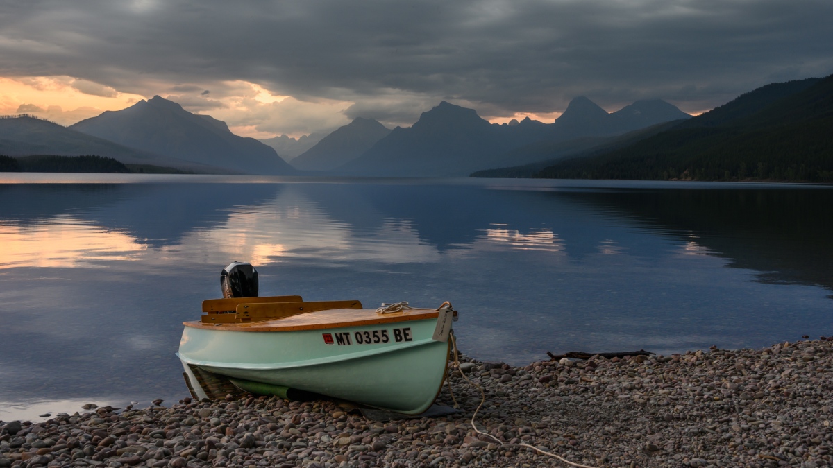
Corey wanted to catch the sunrise at Lake McDonald, so we woke up extra early to drive in the dark to the Park entrance.
When we got to the lake, there were some pretty serious clouds covering the eastern horizon; no fiery sunrise for us this morning.
Even so, the smoke in the air from the western wildfires gave everything a yellow hue, making for some very unique pictures.
The rocks in Lake McDonald aren’t quite as colorful as the pictures let on; they are still unique though!One of my new desktop background images!loonslooooooon
Once we decided the ‘Sunrise’ was done, we had a little bit of time to make our way up Going to the Sun Road.
I had rented a 70-200 f/4 for the wedding, and it really came in handy here. The longest lens I had owned up to that point was probably 140mm, so the extra zoom really allowed me to try some new things.
Handheld smooooth waterThese were from a secret, off-trail spot200mm power!
We drove up the road a few more miles and stopped at a bend in the river, where there was a nice surprise:
Do you see him?
I’ll zoom in a bit:
I actually saw two black bears just down the road from me! Successful trip!
At this point, we knew we had to head back to get ready for the wedding. We stopped one last time at the point we had shot the sunrise.
Look at those blue skiesIf you were SUPing and kayaking in late August 2020 in Glacier, let me know
Thanks for reading, let me know if you enjoyed the pictures!
Green leaves were emerging from the cornfields zipping past. It was June, after all, and everything was excited to be alive again. I was lost in thought and I almost missed my turn back home. Tuesday nights were one of our open nights, and I was thinking about what I was going to do after work.
My phone started buzzing: Kadi was calling. She was home, and wanted to figure out what to do for dinner. We conferred for a bit before agreeing I could grab some squash and mushrooms to saute and put over rice. I love mushrooms, Kadi doesn’t. I was excited.
I got home after going to the store and put the things away in the fridge until we were ready. I’ll probably put garlic and paprika on. Kadi was running around grabbing some things.
She suggested we go for a drive. This was a bit unusual, but we were pretty well mired in our after-work routine at this point in the year, and we wanted to change that.
Kadi got into the driver seat and started driving. She didn’t mention any plan, and I was happy to enjoy the mystery. We headed west. Out of Longmont, into the foothills. Out of the foothills, into the mountains. I wish I had brought my camera!
She drove us up a dirt road, parked at the end, and got out of the car. She sauntered over to the wooden sign, took a look at it, and said “Yep!”. She walked back to her car, opened the hatchback, and revealed our backpacking bags, fully packed and ready to go.
My mind raced: “But…what about the mushrooms…?”
sneaky Kadi!
I think my brain just sort of short-circuited, and the next step it had in the chamber dry-fired. I was so excited! Kadi had planned a whole trip, gotten our bags packed (very impressive for only a one-time backpacker), and gotten us out the door before dark…on a Tuesday!
The weather called for a slight chance of rain, but we had our rain gear. The sun was about to set, but we had our head lamps. Weeknight backpacking is all about being flexible.
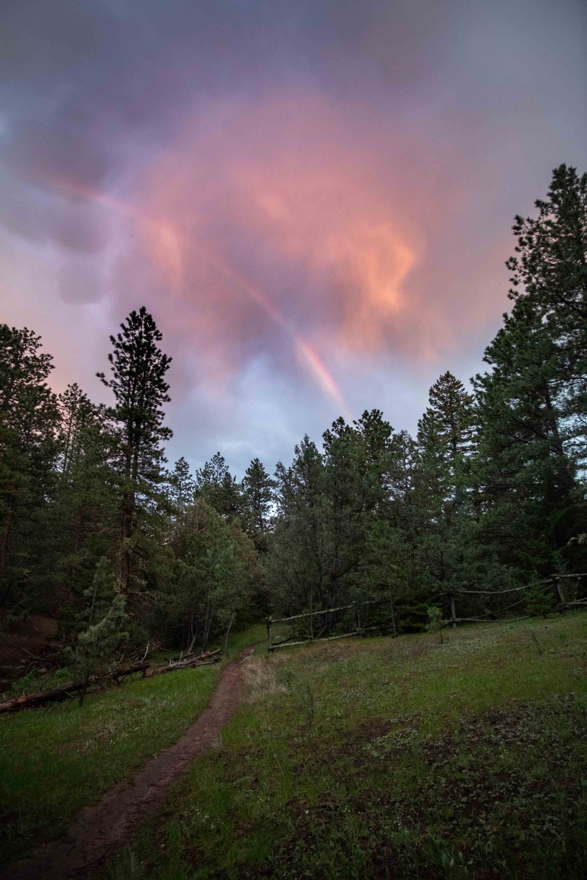
Kadi diverged that she didn’t have a plan for distance, and we could just camp whenever we find a suitable camp site. We hiked down through the lush June mountains as it slowly darkened around us. A rain cloud looked at us from above the west ridge.
Everything came together in one moment–an opening in the trees, an opening on the horizon to let the sun through, an opening in the clouds to release the rain. A rainbow greeted us as I threw my bag down to get the wide lens out.
The rain cloud passed, and the sun set. A large field presented itself in front of us, and we figured it was time to relax.
ol’ tried and true
We found a nice site beside the burbling brook we had been following for these two miles. Though we didn’t have mushrooms, our instant mashed potatoes with cup-o-soup mixed in hit the spot.
It was very dark by the time we had finished dinner. We got the bear bag hung, brushed our teeth, used the little boy’s bush one last time, and got in the tent (after taking a couple night photos, of course!)
Looking back, it was a pretty poor choice of campsite. Though the creek added some nice white noise to get your mind off the eerie silence of the night, it also meant we were down in a valley, where cold air congregates. It had rained the day before, and that moisture didn’t have any chance to evaporate in the damp next to the water. Kadi and I were both cold.
Sunrise was a welcome view. We had a few tasks: Boil some water for oatmeal, pack up the tent and sleeping bags, get the bear bag. Oh, one more thing: hike 2 miles back uphill to the car. Though it made for easy downhill walking yesterday, hiking back uphill was a daunting task.
Cute old cabin
The hike out wasn’t actually bad. There was some beautiful dew on the grass, and the morning sun shining through the trees could reinvigorate even the coldest of campers.
fashion
We finally made it to the car. Kadi was working from home that day, but I still had an hour commute after the hour drive back home. I was a bit groggy through the day, but anytime I found myself daydreaming, I was dreaming about finding another hidden adventure in the mountains.
Where Cameron teaches about his DIY Timelapse slider
Intro
Landscape photography has been a hobby of mine for the last half decade+. It gives me motivation to go see places I might not otherwise, and forces me to stop and enjoy them from different angles I would have missed if I had only hiked. This is surely why I was drawn so quickly to timelapse photography. It is just incredibly interesting to me to watch things move in fast-forward, putting motion into scenes that seem static.
I have taken hundreds of timelapse clips throughout the years (which you can check out on my Youtube Channel, search timelapse). With each timelapse setup I’ve gotten better and better at framing the subject, perfecting the settings, or predicting where the cool clouds will go (mostly impossible, but sometimes I get lucky!). Throughout this learning process, there was one thing that I always wanted to try– a timelapse slider.
Timelapse sliders are long rails with motors which have a platform to mount your camera on that will move slowly and steadily across the length of the rail, giving a very cool motion effect. However, professional rigs cost hundreds (if not thousands) of dollars, so I figured I would have to wait. On the prompting of a friend, however, I figured I could put my Electrical Engineering Degree to use, and started looking to make my own.
I’m all about sharing ideas and helping others, so this post will be presented in the context of making your own slider–whether it’s using my plans and ideas, or your own. Enjoy, and I’m happy to discuss any ideas in the comments!
The Start –V1.0
I broke the process down into three major pieces.
The Mechanical system – The rail, sliding mechanisms, mounting points, all physical things
The Electrical system – What kind of motor to use, what electronics were needed to control it, batteries etc.
Firmware – How would I control it? User experience is rolled into this.
So, here we go, starting with
MECHANICAL SYSTEMS
The Rail
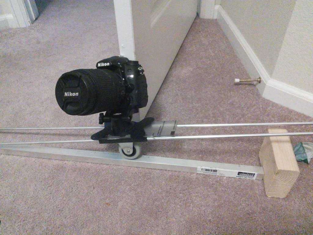
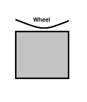
The most important part of the rail system itself is smooth motion across the entire track. My first idea was to get a 1″ caster wheel from the hardware store and have it roll across a 1″ square tube, as seen in this super rough mock-up I made.
This had many problems, but I was determined with this idea and I made my first version with it. The side rails were there for lateral stability, with most of the weight pushing down on the hefty caster wheel.
This was a bad system. The most obvious issue looking back is that the caster wheel wasn’t flat–it was rounded.
This meant that it wasn’t stable whatsoever. Even though I was careful to put the center of gravity over the top of the pivot point of the wheel, any motion meant that it would wobble, a terrible thing for timelapses. In the end, this whole idea was scrapped, and I moved on to:
V 2.0
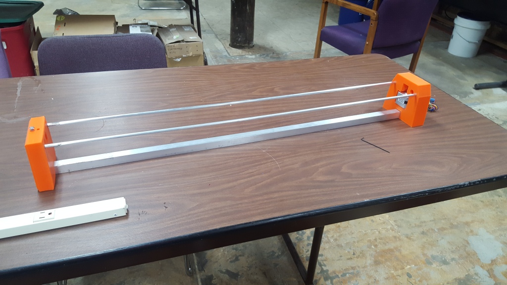
Learning from the experience of my first run, I came back to the project after more than a year. I wanted to be a bit more professional with it, and had learned a bit more about designing 3D models with Blender (I know, still not professional…but it works!).
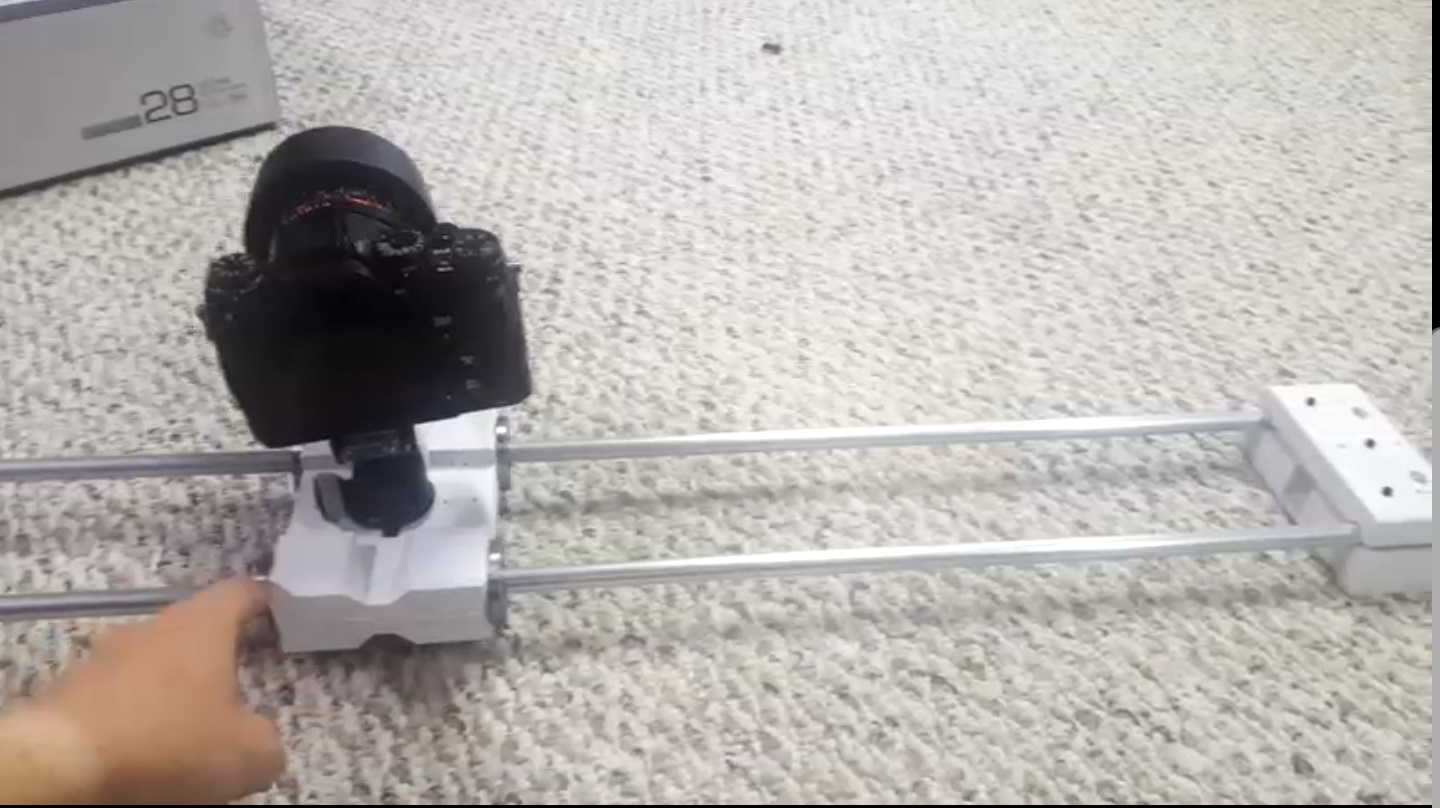
I started with a true rail system, designing around 1/2″ hollow aluminum tubes (still from the hardware store) placed about 3″ from each other. This gave the platform four stable corners, meaning I didn’t have to worry about it wobbling.
The next problem to solve was making it slide smoothly. I found that the term I should look for was ‘Linear Bearings’, just meaning they’ll be sliding in a straight line. 3D printers use these, and therefore have made these very cheap. Unfortunately they use much smaller rods than my 1/2″ rails, so I couldn’t use those exact pieces.
After searching for a while, I found things called ‘Round Flange Linear Bearings‘. These worked perfect for me, since I could embed them into the platform so I could keep the overall package fairly small. These are what I ended up using, but I would look at skateboard bearings if I were to do this again to clamp on either side of the rail, since they are probably lighter and cheaper.
The tubes are attached on either side to the front and back blocks, which sandwich them between two 3D printed parts to tighten them in and keep them stable. These are the basics of the mechanical systems, so that will bring us to the next major piece.
ELECTRICAL SYSTEMS
Locomotion
This system is sort of halfway between mechanical and electrical, so I feel it’s fitting to transition with it. Looking at existing designs, there are a few different common options: a toothed belt looped with a gear on the motor, a static toothed belt with the motor crawling across it, spooling a string on the motor shaft, or rotating a threaded rod. I chose the first toothed belt option, since I already had a stepper motor, and it seemed to be the most straightforward and lightest option. This option worked well on V1, so I kept it in V2.
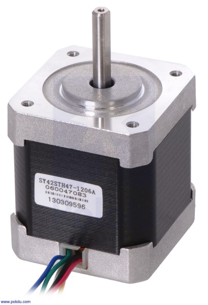
The motor I chose is another 3D printing staple, a standard NEMA 17 stepper motor. They have enough torque to directly move the platform without a gearbox, and are pretty cheap online (~$20). At first I attempted to drive the motor directly, but after losing lots of torque due to incorrect timing I decided to simply buy an off-the-shelf stepper motor driver, I think it was the Easy Driver, bought on SparkFun.
The Electronics
In my EE coursework, I used the Texas Instruments MSP430 microcontroller extensively. I had even already written a program to control my stepper motor, so it was an obvious choice to use this as the base of my control unit. I decided that I definitely wanted different traverse durations so that I had flexibility for different shooting conditions. Here is a hand-drawn block diagram for the electronics:
The MSP430 has 4 inputs: 3 buttons and one potentiometer (knob). Two of the three buttons are limit switches (front+back buttons), which tell the microcontroller when the platform had reached one end or the other. The third button (called the “Go” button) is simply that: when pressed, it starts!
The potentiometer is the adjustable control of the machine, dictating how quickly the platform will move across the rail. The microcontroller reads the analog voltage on the dial, then converts it to 5 discrete steps to determine the speed. We’ll get into this later in the firmware section.
It has 7 outputs: 2 status LEDs, a signal for a transistor that would control the motor, and finally 4 stepper motor control wires.
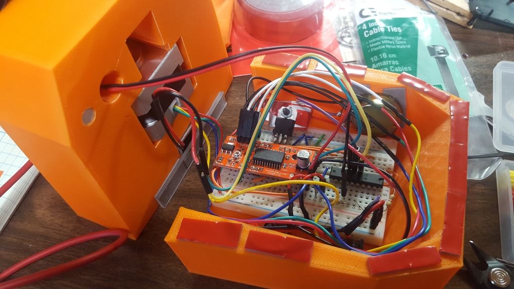
I initially made this circuit on a breadboard and stuffed it into the end section of the old slider.
It was very messy, and I barely fit everything in! Not to mention that it was all held together by double stick tape…definitely learned a lot from that first one, but looking back at it makes me appreciate how much I’ve learned. Here’s a schematic diagram of all the electronics. Really pretty messy, but simple.
The 12V input from the battery is regulated down to 3.3V with a linear regulator for the digital logic. Three switches attach to GND for the MCU to know they’re pushed, then some headers (on the right side) to solder onto the Easy Driver board. Throw a couple current limiting resistors for the MCU and LEDs, and there you go!
Since I wanted V2 to be much better, I made a custom PCB for it. I hadn’t made one since my Junior year in college, so it was a really good way to get back into it (and sparked my interest in it, since now I make them full-time!). I used a trial version of Altium to make it with through-hole components on a two sided board.
I got the PCB manufactured by PCBWay.com, which I highly recommend for bare boards. I think I got 12 for $20 (including shipping), which is a killer deal, though it did take a number of weeks to arrive from China (3-4 weeks).
The batteries I use are some drone batteries I had lying around, 3S lipo batteries that give 10.5-12.5V volts depending on how charged they are. Though these work fine and give more than enough current, they are incredibly bulky and annoying to charge, travel with, and protect–they will explode if handled improperly. That is why I’m working on another project–but that’s a post for another time. I will post the link here when I finish it!
I bought all the electronics from Digikey for probably around $10, since there aren’t many components. I’ll put a bill of materials together at the end of the post.
FIRMWARE
Because I was using the MSP430, this was programmed in C. I think I’ll just attach the code to this post and talk about the user experience, since there’s only so much explaining of code you can do before just showing it.
When designing the user interface, I wanted it to be simple and fast. The user basically only has two options after switching it on: change the knob, or pressing ‘Go’. The knob is split up into 5 discrete steps within the analog voltage range, currently set to 5min, 10min, 20min, 30 min, and 60min. This number is currently hardcoded into the program and needs to be manually calibrated by measuring how long it takes to traverse the rail, but eventually I want to do an automatic calibration when putting new rails on.
There are two status LEDs that allow the slider to communicate back to the user. One is blue and one is red, and down the road that will probably signify something, but I’m only using one at the moment. When the On switch is flipped, the status LED will flash a few times to signify it is on. The user will then turn the dial to the wanted speed, and press the ‘Go’ button. This will make the LED flash 1-5 times, depending on the speed specified, at which point the user will press the ‘Go’ button again to confirm their decision.
You will be able to change the mode depending on if the ‘Go’ button is pressed when turned on, though I’ll have to revisit this, since I want to have several different modes.
I want to implement a ‘shoot move shoot’ long exposure mode, for longer exposures (>.5s). I feel like I may have to implement a display for this with more advanced options, or perhaps try to make a smart phone app that can talk via bluetooth.
The second mode I currently want to make is a ‘fast’ mode, that can be used real-time for smooth video b-roll. For this I might have it change the movement speed in real time with the dial, so it can be used for dynamic shots.
Bill of Materials
This is a pretty simple board. It doesn’t have many components and I think it needs more, now that I have a bit better knowledge of things like bypass caps and TVS diodes. But those will have to wait until Control board V2, so here’s a list of materials for this version:
For this simple board, the cost of the electronics was about $44. The cost of the mechanical systems came to about $38, so maybe around $80 total. I didn’t factor in the use or filament of the 3D printers I used at my work, so this is assuming you don’t have to buy those pieces.
Conclusion
All in all, this project has been a back-burner project for me for years now. It’s functional, and I even took it to New Zealand with me and got some nice timelapses. However, it is a little finicky, and I plan to improve it to make it easier to use. The biggest problem is the batteries–right now I just use one of my old drone batteries, and they are bulky, hard to charge, and a little fragile. I’ve already developed a board that lets me use my Fuji camera batteries to power it, but I need to make a way to connect them. There should be another blog post on the way about it!
If you found this rambling article with hopes of making your own slider, please ask me anything! If you want to copy this design exactly, I would be flattered, and can help you however you need! I didn’t put the full firmware in this post, but I can provide it if needed. I can also post the 3D files on thingiverse if desired.
Thanks for reading this far, and have a happy 2020!